Voltage
Your bog-standard DC motor found in many-a-robot kit tends to be rated for a voltage between 6-12V. Why does the voltage matter? Well the voltage rating for a particular motor indicates the most efficient voltage the motor can run at. Too high a voltage and you start to degrade components due to over-heating, too low a voltage and you may not get enough torque to move it when it is attached to a load. Since the platform I am using in this project did not come with any instructions or specifications, I have no information on what voltage to use with the motors so I’m going to have to rely on a bit of trial and error. A couple of other things to keep in mind is that the higher the voltage, the greater the torque the motor can supply, and so the greater the load it can move. But conversely, a higher voltage means a bigger, heavier battery, so our final design will likely be a fine balance between all of these variables.
Current
The second thing to consider is the amount of current the motors will pull. There are two important parameters to consider here:
the operating current
the stall current
1. The operating current is the current used when the motor is operating under normal conditions. Under increasing loads, the current used by the motor increases. In other words, if you power the motor without anything attached, then the amount of current taken by the motor is going to be relatively low – but who wants to just turn a motor in mid-air? We most probably want the motor to do some work for us and actually move something (in my case, a wheeled robot). So why do we need to know the operating current? Well it determines how much energy the wheels will use to move the robot around and has implications on the power requirements of the final design. So it’s good practice to observe the current used by your motor under normal operating conditions. Hooking up one of the motors from the platform kit to a benchtop power supply – I tested the motor at a standard voltage of 6V. Without any load on the motor, the current draw was about 200mA (with 2 motors running at 6V, the current went up to approximately 400mA). As eluded to earlier, this is not the operating current but since I haven’t built the platform yet to test the motor under what its load will eventually be, I could not get that information… at least not yet. But this at least gives me a general ball-park figure to think about.
2. The stall current, as the name suggests, is the current used by the motor when the motor stalls, usually due to a load that is so large that it cannot turn. You can simulate this simply by stopping the motor from turning with your hand and then watching the current spike that is generated on a standard benchtop power supply. To avoid frying the sensitive electronics controlling your robot, knowing the stall current is a must. Actual testing of the motor from the kit gave the following results: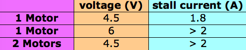 As you can see from the table, the stall current under some conditions was greater than 2A which is the limit of the power supply I’m using so I was not able to get an exact reading for the current draw. However, it was not worth investigating further, since finding a motor driver (see discussion below) that is rated for more then 2A just makes life more challenging, so I have decided to try to run the motors at 4.5V to keep the maximum stall current under 2A.
The Motor Driver
To protect the electronics controlling a robot from excess current draw, we need something in-between the microcontroller (MCU) and the motors. That something is the motor driver which is based on the H-bridge principle. I’m not going to go into the technical details of H-bridges since others have documented them well (just google), suffice it to say that the H-bridge circuit protects the MCU from current spikes while also allowing for control of wheel direction and even braking – pretty neat!
 If you do a search for ‘motor driver’, you get lots of options of motor driver chips to choose from. The key to picking the correct one for your build is to ensure that it can handle the current spike from a stalled motor. In my case, the maximum current generated (by a stalled motor) at 4.5V is 1.8A, making the commonly used L298N motor driver, which has a max current rating of 2A (per driver) an ideal choice. The chip actually contains two separate drivers, each of which can take up to 2A, so each chip will be able to handle 2 motors. I picked up a couple of boards containing the L298N chip (already integrated with peripheral / supporting electronic components) on Amazon for a couple of quid – see picture below – and did a
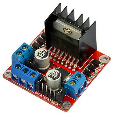 series[easyazon_cta add_to_cart=”default” align=”right” asin=”B00HNHUYSG” cloaking=”default” height=”28″ key=”wide-light” localization=”default” locale=”UK” nofollow=”default” new_window=”default” tag=”tronic03-21″ width=”170″] of tests with a voltmeter to verify they were working as described. By inputing 5V into these modules, approximately 4.5V was obtained on the outputs to the motors. So these boards would work well with the standard 5V used to power the AVR.
Forward, Reverse and Turning
Using the ADC function of the AVR, forward and reverse motions of the motor driver can be controlled through the forward and reverse movements of the joystick. Sampling a second ADC on the AVR connected to the side-to-side movement of the joystick allowed the wheels on either side of the robot to rotate in opposite directions, allowing for a ‘turning-on-the-spot’ type of motion.
stay tuned for further updates …..