Once motor control of the robot itself was established, I thought that it might also be useful to have some sort of moveable webcam sitting atop the platform to provide greater flexibility for remote viewing. There were two potential pathways to take here, either install a couple of servos on the platform at right angles to each other to provide left and right as well as up and down movement for the camera OR to invest in a camera that already incorporates movement as part of its features. Since it was not clear to me which was the better option, I decided to explore both options and leave the final design decision for later. So let’s take a look at the first option I looked at…
Option 1: Servos[easyazon_cta add_to_cart=”default” align=”right” asin=”B00AQJKEF6″ cloaking=”default” height=”28″ key=”wide-light” localization=”default” locale=”UK” nofollow=”default” new_window=”default” tag=”tronic03-21″ width=”170″]
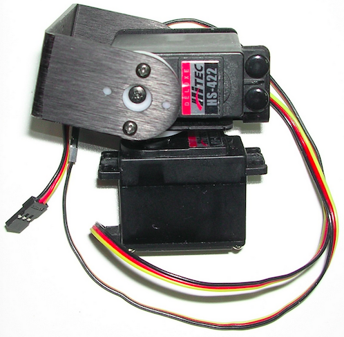 Unsurprisingly there are a number of different makes and models of servos that are recommended for various robotic designs and RC vehicles, but all seem pretty capable of satisfying the requirements of moving a light-weight webcam. So the decision was determined, as is so often the case, by price. I purchased a couple of reasonably-priced standard servos – specifically the Hitec HS-422. Conveniently, they come with all the attachments to mount one perpendicular to the other (as shown in the picture), as well as the armature for mounting the device to be moved (in this case the camera).
Servo Control
The standard way to control servos is to use Pulse-Width Modulation or PWM – do a google search if you want to know how PWM actually works as it is well documented around the internet. Put in layman’s terms, PWM involves pulsing power to the servo electronics so that it only sees current in short pulses. By controlling the length of the pulse, you can determine how far the servo electronics turns its associated motor, and in so doing, determine the specific orientation of whatever is attached to the servo axle (in this case, a camera). So how do we do PWM? Since PWM is useful in different applications, many microprocessors incorporate this feature within their design. The MCUs that I use are the Atmel AVR chips and many of these (if not all?) have PWM as part of the package. Similarly to the Motor Control of the wheels, the servos are controlled using a joystick connected to the ADC function of the AVR microprocessor. The only difference with wheel control is that I am not using PWN to control the wheel motors as it seemed unnecessary (maybe I will change my mind later!). For the servos, ADC sampling of the analogue voltage from the joystick is translated into an incremental increase in the pulse width until it reaches a pre-determined maximum. It was important to have a pre-determined maximum because it prevented the servos from ‘locking’ (causing a nasty current spike – and whine!) at the extremes of it turning circle.
to be continued…