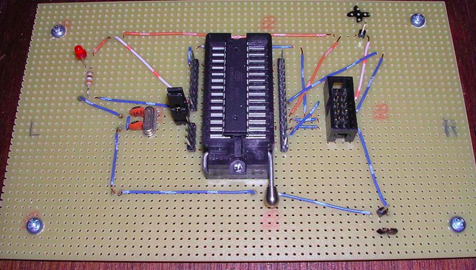
The AVR microprocessor needs to have a program installed on it before it can do any work. Fortunately the folks at Atmel have made this process relatively easy with In-System Programming or ISP. This means that the chip can be programmed even when it is contained within the device that it controls. However, while prototyping on a breadboard, where electronics can be repeatedly changed, the microcontroller often also has to be repeatedly reprogrammed. If you have ever tried ISP on a breadboard, you know that it is a pretty ‘messy’ affair as multiple AVR pins need to be connected to the AVR programmer resulting in jumper-cable anarchy! So to make breadboard prototyping a little more convenient, I use a DIY programming board with a zero-insertion force (ZIF) adaptor to accept the AVR. With another separate ZIF on the prototyping breadboard, I am able to move the AVR back and forth from programming board to breadboard with relative ease.
The first version of the programming board involved some crude wiring and some strip-board. It contains a 15MHz crystal with two capacitors for an external clock source just in case the AVR chip is programmed to use an external source rather than its default internal one. The 5×2-pin header accepts the output lead from the AVR programmer AVR-PG2B, and the pins alongside the ZIF are there to allow the 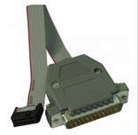 programming board to act as a development board if need be by using female jumper cables. (you will also notice an LED in the picture which was incorporated just to show the board was powered up, but this only worked intermittently due to a wiring misconfiguration and in later versions of the board this has been eliminated.)
[easyazon_cta add_to_cart=”default” align=”left” asin=”B00AQNYX54″ cloaking=”default” height=”28″ key=”wide-light” localization=”default” locale=”UK” nofollow=”default” new_window=”default” tag=”tronic03-21″ width=”170″]